This is the third homework assignment for Lasers and Optomechanics at Syracuse University.
It is due Monday, March 9th, 2026 by 5 pm
You will need to complete the questions in this jupyter notebook and submit it via gitlab
1Homodyne Michelson
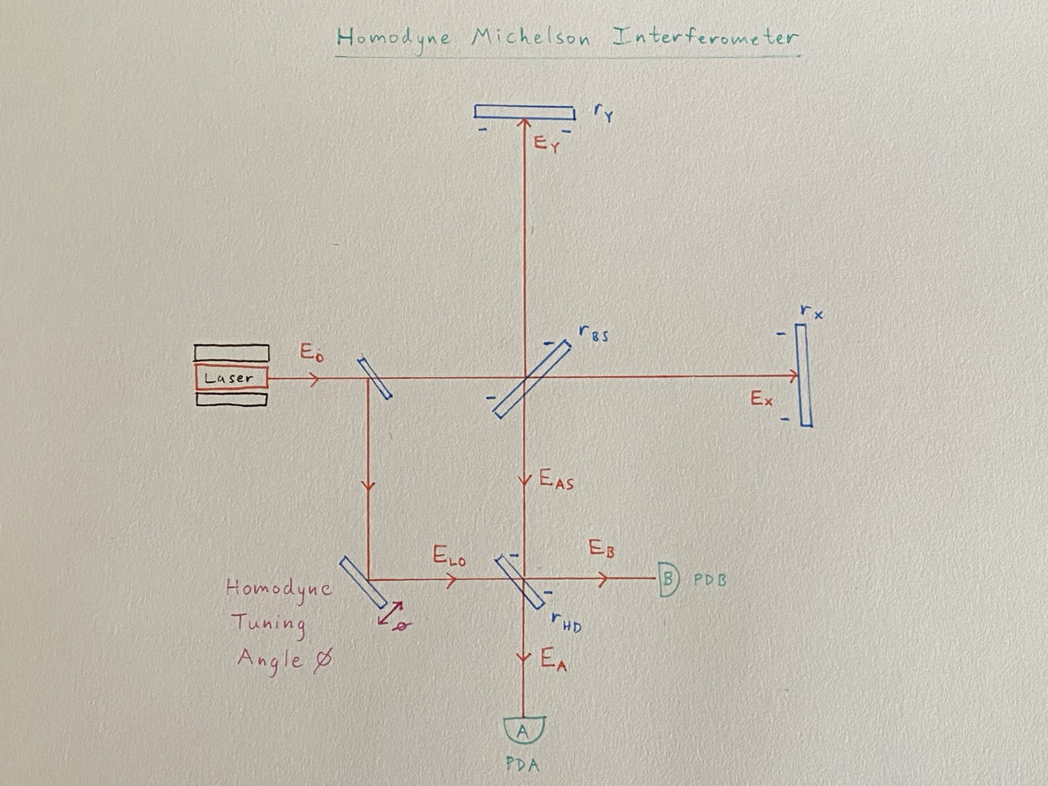
Homodyne Michelson Interferometer Diagram
1.1Adjacency Matrix
Set up an Adjacency Matrix for the Homodyne Michelson.
You may choose any electric fields vector you want, but you have to include the explicitly labeled electric fields.
The homodyne angle can be considered as the total phase accrued by the local oscillator field in the pick-off path:
1.2Electric Field Transfer Functions
Invert your Adjacency Matrix minus the identity to calculate the transfer functions from each electric field to every other electric field.
Pick out the field transfer functions from the input to the photodetectors and and
.
1.3Substitutions
Apply the phase change of basis used in class and to your field transfer functions above.
You may also assume a perfect Michelson beamsplitter .
1.4Power Transfer Functions
Calculate the input to power transfer functions and .
1.5Interpretation
How do and depend on the homodyne angle , and the common and differential Michelson phase and ?
Can we manipulate the homodyne angle to detect the differential phase ?
Can you think of any problems you might run into if you tried to actually set up a homodyned Michelson?
2Asymmetric Michelson
Suppose you have a Michelson interferometer with the X-arm much longer than the Y-arm:
In this problem, we will calculate the full frequency response transfer functions of the Michelson
I recommend using an algebra helper like Mathematica or sympy for this problem. You may convert your answers to LaTeX using TeXform in Mathematica or some such similar function for sympy.
2.1Field tranfer functions
Derive the electric field transfer functions for the following:
where is the input electric field ,
is the field reflected from the X-arm mirror,
is the field reflected from the Y-arm mirror,
and is the field at the antisymmetric (or transmission) port.
Use for the beamsplitter reflection and transmission,
for the X and Y mirror reflections, and
for the single-pass phase accrued by the field as it propagates in the X-arm or Y-arm.
2.2End Mirror Modulation
Now, suppose we apply some common modulation to both end mirrors:
Write what the new arm reflected transfer functions are for:
Hint: Remember that you should end up with three distinct fields at and
2.3Propagate to the antisymmetric port
Propagate your new transfer functions to the antisymmetric port, and compute a new .
Be careful here.
Consider carefully what is for each of your electric fields as they propagate back to the beamsplitter, accruing some phase .
Should each field accrue the same phase?
2.4Calculate the power response
Calculate the power response to the common motion .
This is a lot of algebra, I recommend Mathematica or sympy to help you make sure you get things right here.
You may find it useful to express your arm phases in the common and differential bases again, since you have already incorporated the time-dependent term as two additional sideband terms:
You may assume an ideal beamsplitter
and balanced arms
and small modulation from the end mirrors
Answer:
2.5Demodulate the power term
Calculate
by integrating over one cycle of while multiplying by and , respectively.
Does your answer for seem familiar?